amplifIR
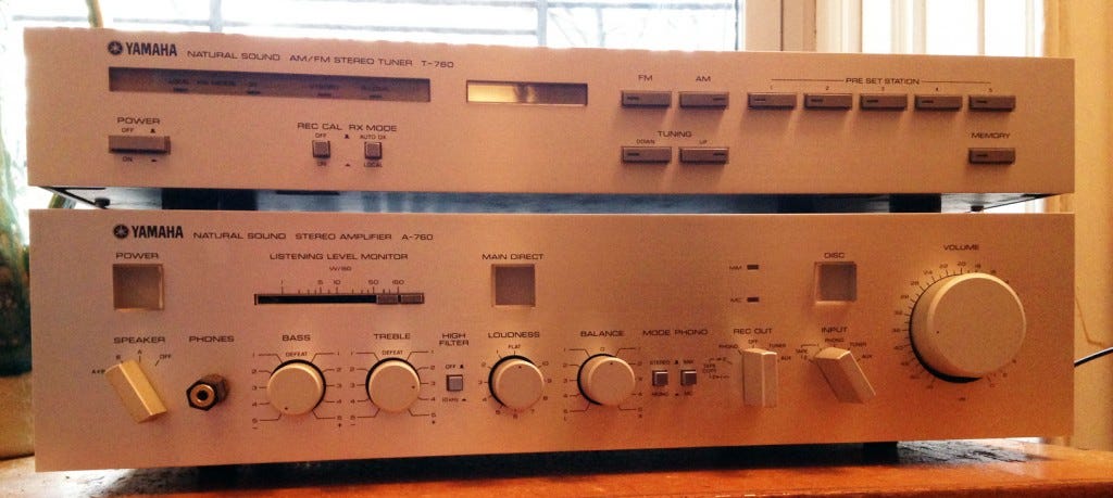
I love my Yamaha A-760 Natural Sound Stereo Amplifier (circa 1981). I came across it on craigslist six years ago, and I knew that it was the one when I discovered this restoration project online. One doesn’t typically put that much effort into something without a good reason. It only confirmed my excitement when I learned that I was buying it from its original owner, who still had the owner’s manual.
But, as is always the case, my true love has been tested over time. The biggest challenge? This amp hails from an age before most A/V hardware was equipped with remote controls, and I am a lazy, modern human. To make matters worse, TV seems to be mixed so erratically these days — I feel like I’m constantly fine-tuning the volume!
I spent years despairing over this. (Time that could’ve been better spent purchasing a new receiver? No, thank you.) Fortunately, I also spent this time leveling-up my physical computing skills, and eventually found a video tutorial online by Ian Johnston, who had tackled a similar project using an Arduino and a motorized potentiometer in place of the existing volume knob. Perfect! I called upon my friend, storied recording engineer Jon Altschuler, to help me make sense of Ian’s schematics and the byzantine Yamaha service manual (PDF), and together we devised a shopping list and plan of action.
…and then, this project sat on the shelf for almost a year, during which my girlfriend and I moved into our new ginkgo-adjacent apartment and the precious A-760 sat in a moving box.
But! It’s the holidays! And my girlfriend’s parents are coming to visit. Can’t have them see our apartment without a fully-functional A/V system, right? So instead of cleaning the house, I spent this week tricking out my amp. Here’s what the final project looks like:
This project utilizes the following components:
- Arduino Uno
- Bourns PRM162-K415K-104A2 motorized potentiometer
- Hitec HS-311 servo
- Seeed Motor Shield v2.0
- SMAKN DC-DC Buck Converter
- 7v-12v AC-DC adapter (I used this Plantronics model)
- TSOP38238 IR sensor
- Sony RMVL620 universal learning remote
…and Arduino code that can be downloaded via github and leverages the following sources:
- Pioneer Amplifier Repair & Motorized Volume Control Conversion
- Seeed Motor Shield library
- IRremote library
- Arduino IDE servo library
- Watchdog reset
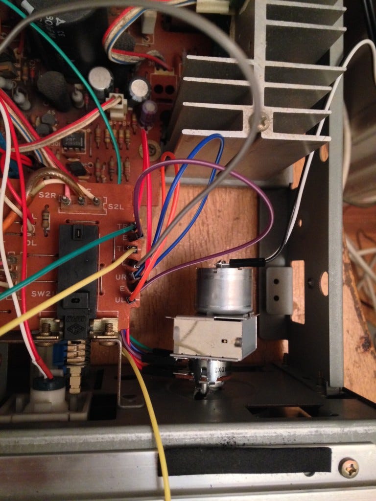
The actual steps of this project will vary depending on the internal configuration of your amplifier. In my case, I had to remove a daughterboard containing the volume-control potentiometer and a couple of resistors, so I could make space for my motorized pot and my Arduino hardware.
The motorized pot works like any other DC motor. In order to make the motor go forwards and backwards, you create a circuit called an H bridge (or purchase a chip that does the work for you. NYU ITP has a great tutorial on this). To save time, I used the Seeeds Motor Shield (not pictured), which worked with very little setup, thanks to their handy-dandy code library.
I also wanted to control the power switch, which required use of a servo. After much deliberating (and ruing of my non-STEM liberal arts education), I decided that the best approach would be to ziptie the servo next to the internal power switch, and use a thin, strong filament to pull the button. This enables remote control of the switch without interfering with manual control. I used some plastic picture hanging wire and fused it to the plastic button using my soldering iron (with a tip I didn’t mind destroying). The result is kind of hypnotizing:
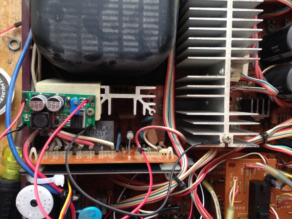
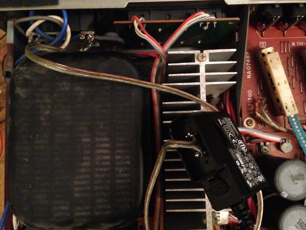
I decided to graft my project onto the existing DC power circuitry inside the amp. Turns out it runs at 47v. When powering the Arduino via its DC jack or VIN pin, it’s best to keep the power supply between 7 and 12v so its internal regulator can work properly. To that end, I used a small DC-DC buck converter to step down the voltage and feed my project. I was able to stick it on top of a heatsink adjacent to the gigantic DC transformer inside the amp.
This worked great, with one exception. Because the onboard DC power is controlled by the amp’s power switch, once the Arduino shuts off the power it can’t turn itself back on again! Kind of like The Most Useless Machine Ever.
To resolve this, I removed the DC-DC buck converter and replaced it with a small 9v AC-DC adapter (you can use any adapter that outputs 7v-12v DC and is small enough to fit inside your amplifier), wired directly to the 110v AC current inside the unit. This way the Arduino receives continuous power, independent of the amp’s DC transformer.
For the infrared receiver, I used a standard IR sensor, which I stuck in the space hollowed out for the Yamaha’s Listening Level Monitor, a slider I never use. The IR library has an example that allows you to use the Arduino’s serial monitor to listen for incoming signals, so I jotted down the commands for vol up, vol down, mute and power from my universal remote. Thus, my setup essentially mimics a Sony amplifier.
The biggest hurdle is that both the motor shield and the servo library require use of the same hardware PWM timer on the Arduino, so the volume control would stop working once the servo was attached, even though there wasn’t a direct pin conflict. I was unable to figure out a way around this problem, and it looks like I’m not the only one. For now, my ugly hack is to reset the Arduino board every time the servo is triggered. This is fairly instantaneous and it allows the volume control to keep working properly.
So, what does it look like put together? It’s a little messy, but it works:
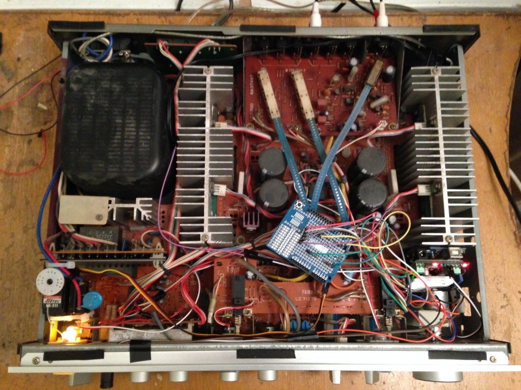
My next revision will definitely be smaller, likely using an Arduino Nano with a single hand-made circuit instead of an Uno with a big shield, and may add controls for other amp features, such as input source.
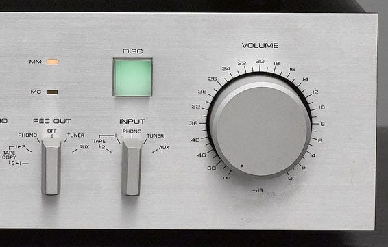
Oh, and I guess I should note that other amps go to 11… but this one STARTS AT INFINITY.
